Progressive Nitrous Controls Overview
The Pro-M EFI PCM will progressively ramp up the flow of nitrous supplied to the engine, allowing for a smooth transition up to whatever amount of nitrous you want to deliver, reducing tire spin, resulting in better track times, while minimizing abuse to your drivetrain and your chassis, and extending the life of the nitrous supply in the bottle. At the same time, the Pro-M EFI PCM will ramp down the spark advance and add extra fuel to richen the mixture to the desired ratio when spraying the nitrous. Not only will this improve your numbers at the track, it also makes using nitrous oxide truly practical for the street.
The progressive nitrous controller is an integral part of the Pro-M EFI PCM. The only other components necessary for the nitrous oxide system installation are the nitrous system itself, and a High Current Driver, available from Pro-M Racing.
The Pro-M EFI Progressive Nitrous Control System is easy to use, and easy to program. In fact, the majority of this has already done for you. You simply need to tailor it to your needs. Below is an overview of the nitrous controls.
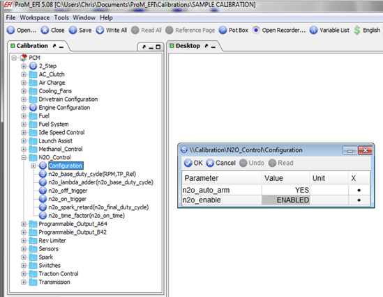
There are two parameters in the “Configuration” section. These are “N2O_auto_arm”, and “N2O Enable”.
Change the “N2O Enable” to “Enabled” to activate the nitrous control system in the Pro-M EFI PCM.
The “N2O_auto_arm” feature allows you to choose between two different options to “Arm” the nitrous controls.
Setting the Auto Arm feature to “Yes” means that the system is always armed and ready to deliver nitrous anytime the conditions for doing so are met. This setting is what you would typically use on the street. We should mention here that if the “Auto Arm” is set to “Yes”, and if you have our Traction Control system enabled, the nitrous will be shut down during a traction control event, then ramped back in when traction is restored.
Setting the Auto Arm feature to “No” means that you will need to manually arm the nitrous controls with the “Arm” switch. A setting of “No” would be useful for drag racing. You would do your burn out, and pull up to the starting line, where you would “Arm” the system with the Arm switch. Nitrous will be delivered the first time the conditions for doing so are met. If you got into trouble during the run and had to let up on the throttle, the nitrous will not spray again until you re-armed the system with the “Arm” switch, which would help you regain control of the vehicle. We should also mention here that if you have our Traction Control system enabled, the Nitrous Control system will be shut down when wheel slip is detected and will not be allowed again until you push the “Arm” switch.
The “Configuration” section is shown below.
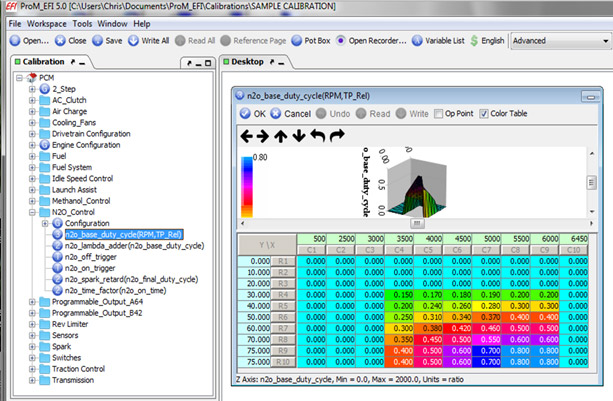
The “N2O_Base_Duty_Cycle” table is shown below. This table determines how much nitrous will be delivered based on throttle position and engine RPM.
At the left of the table is throttle position. More specifically, it is relative throttle position, which is why it only goes up to “75”. Relative throttle position is represented in degrees of throttle plate movement. A throttle plate will rotate roughly 75 degrees to go from closed to wide open throttle. Relative position is the most appropriate way to look at throttle position in this case.
Across the top of the table is engine RPM. The entries range from 500 to 6450 in this example. You can make those entries any value you want, but keep in mind that you do not want to spray nitrous at an RPM higher than your Rev Limit setting, which in this example is 6500 RPM. So the high end setting of 6450 is appropriate in this case.
The entries in the table represent the “Duty Cycle” being sent to the nitrous and fuel solenoids. Duty cycle represents the ratio of “ON” vs. “OFF” time. A duty cycle of “0” means there is no current being sent to the solenoids. A duty cycle of “1” would mean that the solenoids are “ON” 100 percent of the time. A duty cycle of “0.5” would mean that the solenoids are being rapidly pulsed on and off, and that they are “ON” 50% of the time, which means they would be spraying at a rate of 50% of the capacity of whatever nitrous (or fuel) jet is installed.
You can see in the table below how we have used Relative Throttle Position, Engine RPM, and Duty Cycle to progressively “Ramp Up” the amount of nitrous delivered to the engine.
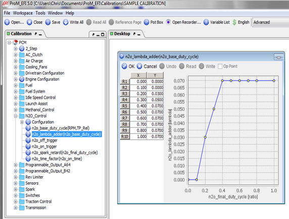
The “N2O_Lambda_Adder” is shown below. The entries on the left represent the duty cycle being sent to the nitrous and fuel solenoids. The entries on the right represent the amount of fuel that will be added via the fuel injectors when nitrous is being sprayed. This should not be confused with the fuel that will be added via the nitrous system's fuel solenoid. The purpose of this table is to adjust the desired lambda to a figure that is appropriate when spraying nitrous.
The name of the table is “N2O lambda adder”, but it was given that name only to avoid confusion. It is a lambda subtractor. The values in the right column will be subtracted from the base lambda, resulting in a lower lambda value, resulting in more fuel. When spraying larger amounts of nitrous, say a 300 hp shot, the general rule of thumb is an AFR of 12.5 to one. Smaller shots, say around 100 hp, require little change to the AFR at all. Using this table, we can adjust the target lambda to a value that is appropriate for nitrous being sprayed. The Pro-M EFI PCM will then use feedback from the wide band O2 sensors to hit the target AFR.
Next are the “ON” and “OFF” triggers. Use the On and Off triggers to determine when the PCM can, and cannot, deliver nitrous to the engine. This feature makes our nitrous controller the most versatile one on the market. You can choose whatever variable you want from the entire list of variables in the calibration tool to trigger your nitrous. And you can do this by simply telling the PCM what to do, rather than having to make wiring connections to inputs on a separate controller. You can also use a combination of two variables if you'd like. Below are a few examples.
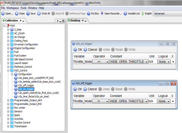
If you were drag racing, you might simply want to trigger the nitrous as a function of throttle position. The example below shows how you would do this. In this example, the PCM will deliver nitrous only when at wide open throttle. Examples of other options would be to use relative throttle position, or TPS volts as the trigger.
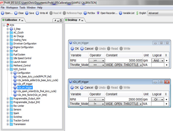
Below is an example of using two variables. In this example, the PCM will be able to deliver nitrous only when the RPM has exceeded 3000 RPM and the throttle is wide open. Notice that the “OFF” trigger is set so that when the RPM goes below 2800, or when “throttle mode” is not equal to wide open throttle, the PCM will stop delivering nitrous.
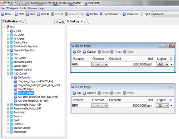
If you are using the nitrous on the street, we'd suggest you leave the triggers as a function of RPM as in the example below. The calibration comes pre-configured this way. Using this example, the PCM will be able to deliver nitrous anytime the RPM is above 3000 RPM, which is the appropriate starting point for most applications.
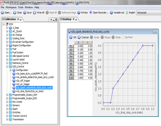
The “N2O spark retard” table is shown below. The entries in the left column represent the duty cycle being sent to the nitrous and fuel solenoids. The entries in the right column represent the amount of spark advance, in degrees, that will be removed from the spark advance.
Generally, you will want to remove 2 degrees of advance for every 50 hp shot of nitrous. The example below would be appropriate for a 100 hp shot. The “N2O spark retard” table allows you to remove an appropriate amount of advance for the Nitrous, without modifying the Base Spark table. This allows the PCM to command an appropriate amount of advance in all cases, even in the event of component failure.
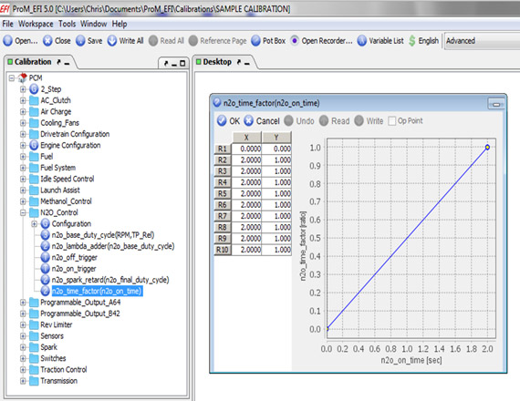
The “N2O time factor” table is shown below. This table allows you to create a “ramp up” to the duty cycle being commanded in the “N2O base duty cycle” table, which serves to further smooth the delivery of nitrous to the engine. More importantly, it keeps the delivery of nitrous in check should the tires break loose. This is an important safety feature to understand.
If you put your foot to the floor, and lost traction, you would be at wide open throttle, and at a high RPM almost immediately. This would result in a duty cycle to the nitrous solenoids that is immediately very high, which could allow things to get out of control quickly. The “N2O time factor” table stops this from happening.
The column on the left represents the amount of time since the nitrous started being delivered to the engine. The column on the right is a multiplier. For instance, if the time in the left column was “2”, and the multiplier in the right column is “1”, it would take two seconds to ramp up to the commanded duty cycle in the “N2O base duty cycle” table. If the multiplier was 0.5, it would take two seconds to reach half of the commanded duty cycle. This allows you to completely customize the delivery of nitrous, allowing you to create a “curve” that will keep your tires near the limit of traction to achieve the best track times.
Creating a custom curve is probably overkill for most street applications, but it can be very useful for drag racing. For most applications, we can keep this pretty simple. The table below is an example of the entries you would make if you just wanted a simple ramp up that is 2 seconds long. If you are racing, you can experiment with this table until you achieve the best acceleration possible while still maintaining traction.
If you are using our Traction Control system, you'll likely want to keep this simple as shown below, since the Traction Control system negates the need to create a custom curve. Since our Traction Control System is an integral part of the Pro-M EFI PCM, costs you nothing to use, and works hand in hand with our Nitrous controls, this is the recommended method.
PRO_M EFI How-To Videos